High-Level View
Here is a quick overview of the components of a digital clock at a high level.
At the heart of the clock there is a piece that can generate an accurate 60-hertz (Hz, oscillations per second) signal. There are two ways to generate this signal:
Advertisement
- The signal can be extracted from the 60-Hz oscillations in a normal power line. Many clocks that get their power from a wall socket use this technique because it is cheap and easy. The 60-Hz signal on the power line is reasonably accurate for this purpose.
- The signal can be generated using a crystal oscillator. Obviously, any battery-operated clock or wristwatch will use this technique instead. It takes more parts, but is generally much more accurate.
The 60-Hz signal is divided down using a counter. When building your own clock, a typical TTL part to use is a 7490 decade counter. This part can be configured to divide by any number between 2 and 10, and generates a binary number as output. So you take your 60-Hz time base, divide it by 10, divide it by 6 and now you have a 1-Hz (1 oscillation per second) signal. This 1-Hz signal is perfect for driving the "second hand" portion of the display. So far, the clock looks like this in a block diagram:

To actually see the seconds, then the output of the counters needs to drive a display. The two counters produce binary numbers. The divide-by-10 counter is producing a 0-1-2-3-4-5-6-7-8-9 sequence on its outputs, while the divide-by-6 counter is producing a 0-1-2-3-4-5 sequence on its outputs. We want to display these binary numbers on something called a 7-segment display. A 7-segment display has seven bars on it, and by turning on different bars you can display different numbers:
To convert a binary number between 0 and 9 to the appropriate signals to drive a 7-segment display, you use a (appropriately named) "binary number to 7-segment display converter." This chip looks at the binary number coming in and turns on the appropriate bars in the 7-segment LED to display that number. If we are displaying the seconds, then the seconds part of our clock looks like this:
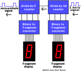
The output from this stage oscillates at a frequency of one-cycle-per-minute. You can imagine that the minutes section of the clock looks exactly the same. Finally, the hours section looks almost the same except that the divide-by-6 counter is replaced by a divide-by-2 counter.
Now there are two details left to figure out if you are building a real clock:
- The clock as designed here does not understand that at 12:59:59 it is supposed to cycle back to 1:00. That is a messy little problem, and there are a couple of ways to solve it. One technique involves creating a little bit of logic that can detect the number 13 and reset the hour section back to 1 (not zero). Another technique involves using an adder. For our purposes, it is easier to deal in military time, because military time includes a zero hour.
- We need a way to set the clock. Typically this is handled by gating higher-than-normal frequencies into the minutes section. For example, most clocks have "fast" and "slow" set buttons. When you press the "fast" button, the 60-Hz signal is driven straight into the minutes counter. When you press the "slow" button, a 1-Hz signal is driven into the minutes section. There are other possible techniques, but this one is the most common.
Now let's see what we have to do to build a real clock!