Oscillator and Capacitor
In the last section, we saw that transformers need fluctuating current to work properly. The flash circuit provides this fluctuation by continually interrupting the DC current flow -- it passes rapid, short pulses of DC current to continually fluctuate the magnetic field.
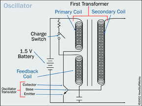
The circuit does this with a simple oscillator. The oscillator's main elements are the primary and secondary coils of the transformer, another inductor (the feedback coil), and a transistor, which acts as an electrically controlled switch.
Advertisement
When you press the charging button it closes the charging switch so that a short burst of current flows from the battery through the feedback coil to the base of the transistor. Applying current to the base of the transistor allows current to flow from the transistor collector to the emitter -- it makes the transistor briefly conductive (see How Amplifiers Work for details).
When the transistor is "switched on" in this way, a burst of current can flow from the battery to the primary coil of the transformer. The burst in current causes a change in voltage in the secondary coil, which in turn causes a change in voltage in the feedback coil. This voltage in the feedback coil conducts current to the transistor base, making the transistor conductive again, and the process repeats. The circuit keeps interrupting itself in this way, gradually boosting voltage through the transformer. This oscillating action produces the high-pitch whine you hear when a flash is charging up.
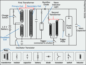
The high-voltage current then passes through a diode, which acts as a rectifier -- it only lets current flow one way, so it changes the fluctuating current from the transformer back into steady direct current.
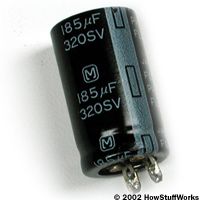
The flash circuit stores this high-voltage charge in a large capacitor. Like a battery, the capacitor holds the charge until it's hooked up to a closed circuit.
The capacitor is connected to the two electrodes on the flash tube at all times, but unless the xenon gas is ionized, the tube can't conduct the current, so the capacitor can't discharge.
The capacitor circuit is also connected to a smaller gas discharge tube by way of a resistor. When the voltage in the capacitor is high enough, current can flow through the resistor to light up the small tube. This acts as an indicator light, telling you when the flash is ready to go.

The flash trigger is wired to the shutter mechanism. When you take a picture, the trigger closes briefly, connecting the capacitor to a second transformer. This transformer boosts the 200-volt current from the capacitor up to between 1,000 and 4,000 volts, and passes the high-voltage current onto the metal plate next to the flash tube. The momentary high voltage on the metal plate provides the necessary energy to ionize the xenon gas, making the gas conductive. The flash lights up in synch with the shutter opening.
Different electronic flashes may have more complex circuitry than this, but most work in the same basic way. It's simply a matter of boosting battery voltage to trigger a small gas discharge lamp.
For much more information on camera flashes, including flashes that "read" the subject in front of them, check out the links below.