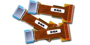
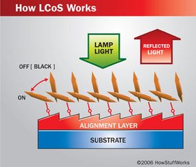
A LCoS microdevice reflects light using liquid crystals.
Photo courtesy JVC
Most people grew up watching a cathode ray tube (CRT) television. These televisions, while bulky and heavy, had a great picture as long as they got a clear signal. CRT sets are still what a lot of people think of when they think of TVs.
But if you've shopped around for a TV recently, you've seen that now there are a lot more options. CRT still works well for screen sizes up to 40 inches. But if you want a larger screen, a flat panel TV, widescreen model or HDTV compatibility, you'll have to choose from several types of sets, including liquid crystal display (LCD), digital light processing (DLP) and liquid crystal over silicon (LCoS).
Advertisement
LCoS isn't particularly new technology, but it wasn't readily available until recently. In this article, we'll look at the technology behind LCoS, how it provides a clear picture and how manufacturers have addressed issues with black levels and contrast.
Thank You
Thanks to Daniel Guzman for his assistance with this article.
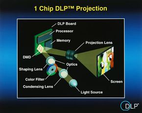
A DLP system using one DMD and a color wheel to provide color.
Photo courtesy Texas Instruments
The most common use for LCoS is front- and rear-projection televisions. The setup is a lot like what you find in a DLP system. DLP uses a digital micromirror device (DMD) to create a picture using a process that's like making a mosaic out of small, square tiles. The DMD contains millions of microscopic mirrors that reflect light from a lamp. Each mirror creates one pixel of the final image.
The mirrors flip back and forth between their "on" and "off" positions very rapidly. When mirrors are on, they point toward a projection lens. The longer a mirror is in the on position, the brighter the pixel it creates. Mirrors creating black pixels remain off. In most DLP televisions, a color wheel spins between the lamp and the DMD, adding red, green and blue light to the picture. The viewer's eyes combine these colors to create the finished image.
Advertisement
LCoS uses a very similar idea. As with DMDs, LCoS devices are tiny -- most are less than one inch square. Both technologies are also reflective -- the devices reflect light from a source to a lens or prism that collects the light and displays the image. But instead of tiny mirrors that turn on and off, LCoS uses liquid crystals to control the amount of reflected light.
A liquid crystal is a substance that is in mesomorphic state -- it's not exactly a liquid or a solid. Its molecules usually hold their shape, like a solid, but they can also move around, like a liquid. Nematic liquid crystals, for example, arrange themselves in loose parallel lines. Most LCDs use twisted nematic (TN) crystals -- with the application of an electrical charge, the twisted crystals straighten out.
When placed between two polarized panels, the twisted crystals guide the path of light. By changing the direction of the light, the crystals allow or prevent its passage through the second panel. The crystals' ability to change the path of the light is central to its use in LCDs and LCoS systems.
In their twisted state, liquid crystals direct the light so it can pass through the second polarized panel.
Ferroelectric liquid crystals (FLCs), sometimes used in LCoS devices, are crystals which align themselves at a fixed angle away from the normal into orderly rows. They also develop electrical polarity when they come into contact with an electrical charge. Ferroelectric chiral smectic C crystals can switch their orientation very quickly. You can learn more about smectic and nematic liquid crystals at Kent State University's Liquid Crystal Institute.
The liquid crystal layer in an LCoS microdevice controls the amount of light for each pixel, like the mirrors do in a DMD. But making the picture requires more than just the microdevice -- it also requires lenses, mirrors and prisms.
Semiconductors and LCoS
Silicon is a semiconductor. Semiconductors are used in diodes, which allow current to move in only one direction, and transistors, which either amplify currents or switch them on and off. The silicon in an LCoS device is often SRAM (Static Random Access Memory) or a CMOS (Complimentary Metal Oxide Semiconductor) photo sensor.
Advertisement
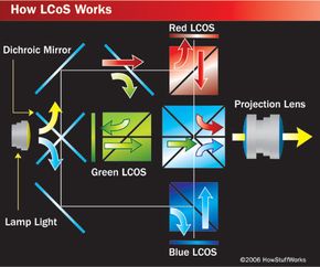
Projection and Color
In LCoS projection, light from a lamp reflects off of the microdevices and is eventually projected through a lens.
HowStuffWorks.com
It takes several steps to create a picture in an LCoS television. The process includes a high-intensity lamp, a series of mirrors and microdevices arranged into a cube, a prism and a projection lens. From beginning to end, here's what happens:
The lamp creates a beam of white light.
The beam passes through a condenser lens that focuses and directs the light. It also passes through a filter that only allows visible light, which helps protect the other components.
The white light is separated into red, green and blue light in one of two ways: The beam passes through a polarizing beam splitter (PBS), which divides the light into three beams, and those beams pass through filters that add red, green and blue. The beam passes through a series of dichroic mirrors that reflect some wavelengths while allowing the rest of the light to pass through. For example, the dichroic mirror can separate red light from the white light, leaving blue and green, and a second mirror can separate the green light, leaving only blue.
The newly created beams of colored light simultaneously come into contact with one of three LCoS microdevices - one each for red, green and blue. We'll look at exactly what happens in the devices in the next section.
The reflected light from the microdevices passes through a prism that combines the light.
Prism directs the light - which now creates a full-color image - into a projection lens, which magnifies the image and displays it on the screen.
Most rear-projection LCoS televisions use this process. Some projectors use a linear setup rather than a cube, and the white light strikes surfaces that color it red, green and blue before reaching the microdevices. A very few systems use only one microdevice along with other methods for adding color. Some examples are color wheels like those found in DLP systems or transmissive dyes on the microdevices themselves. Some systems use additional polarizers or filters to further improve picture quality and contrast.
Advertisement
Without the projection lens, the picture created in this process would be too small to see clearly. That's why LCoS technology falls into the category of microdisplays -- displays that are too small to see without some kind of magnification.
The SXRD Iris
Sony's SXRD (Silicon X-tal Reflective Display) -- their brand name for LCoS -- uses an "advanced iris" to improve black levels. Like the pupil of your eye, the iris opens and closes to change the amount of light that enters the system. Sony was the first manufacturer to include an iris, and several other manufacturers are incorporating similar equipment in sets to be released in 2006.
Advertisement
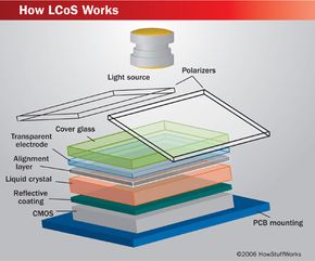
The LCoS Microdevice
Instead of using liquid crystal between two polarized panels like an LCD, an LCoS microdevice has a liquid crystal layer between one transparent thin-film transistor (TFT) and one silicon semiconductor. The semiconductor has a reflective, pixilated surface. The lamp shines light through a polarizing filter and onto the device, and the liquid crystals act like gates or valves, controlling the amount of light that reaches the reflective surface. The more voltage a particular pixel's crystal receives, the more light the crystal allows to pass. It takes several layers of different materials to do this.
From the bottom to the top, here are the components of an LCoS microdevice and what they do:
Advertisement
Printed circuit board (PCB): carries instructions and electricity from the television to the device
Silicon (a chip or sensor): controls the liquid crystal, generally with one transistor per pixel, using data from the television's pixel drivers
Reflective coating: reflects light to create a picture
Liquid crystal: controls the amount of light that reaches and leaves the reflective coating
Alignment layer: keeps the liquid crystals properly aligned so they can direct the light accurately
Transparent electrode: completes the circuit with the silicon and the liquid crystal
Glass cover: Protects and seals the system
The orientation of the crystals relative to the reflective surface changes in the presence of an electric current. Most are nearly perpendicular when off and are angled when on.
The exact materials and configurations differ from manufacturer to manufacturer. Some use nematic liquid crystals and others use ferroelectric crystals. Some use organic alignment layers, which can break down through use and exposure to the high-intensity light from the lamp. Others use photosensitive materials and light to control the impulses to the liquid crystal.
In general, LCoS devices have only a very small gap between pixels. The pixel pitch -- the horizontal distance between one pixel and the next pixel of the same color -- is between 8 and 20 microns (10-6). This reduces or eliminates the "screen door" effect found on some DLP televisions and helps keep the image smooth and uniform.
The system generally creates a good picture, but it does have some pros and cons. We'll look at those next.
Pixels
Many LCoS televisions have SXGA (Super Extended Graphics Array) + or better resolution. That's 1400 x 1050 pixels, for a total of 1.4 million. QXGA (Quantum Extended Graphic Array) sets have even more pixels -- 2048 x 1536, for a total of 2.3 million.
Advertisement
Pros and Cons
JVC Multimedia projector
Photo courtesy HowStuffWorks Shopper
The physical properties of the LCoS microdevice, like the absence of a color wheel and the high fill factor, generally provide a high-quality picture with a minimum of artifacts. LCoS pixels are also smoother than the pixels of other systems, which some people say creates more natural pictures. The rainbow and screen door effects common to DLP televisions don't exist for LCoS. Unlike LCD systems, they're not prone to screen burn-in.
However, most LCoS systems don't have a very good black level, or ability to produce the color black. Televisions with poor black level generally can't produce as much contrast or detail as those with good black level. Since LCoS televisions and projectors use three microdevices instead of one, they also tend to be heavy and bulky. Most require periodic lamp replacement, which can cost several hundred dollars.
Advertisement
Sony SXRD TV
Photo courtesy HowStuffWorks Shopper
In addition, LCoS systems aren't as common as other display types. The reason for this is that LCoS microdevices are difficult to manufacture, and each set needs three of them. Several companies, including Intel, have tried to produce LCoS systems and have abandoned their efforts after consistently low yields in manufacturing.
Check out the links that follow for lots more information on liquid crystals, televisions and related topics.
Other Uses of LCoS
LCoS has other uses besides televisions and projectors. For example, some digital camera viewfinders use LCoS displays. Future applications for the technology include:
Near-to-eye viewing systems, including head-mounted displays
Carnoy, David. "LCoS HDTV's Bumpy Ride into the Living Room." CNET, October 15, 2004. http://reviews.cnet.com/4520-8900_7-5540515-1.html
Cuypers, D., et al. "Assembly of an XGA 0.9" LCoS Display using Inorganic Alignment Layers." ELIS Dept., Kent University, 2002. http://www.elis.ugent.be/ELISgroups/tfcg/publi/eurodisplay2002_p-45.pdf
DeBoer, Clint. "Display Technologies Guide." Audioholics, February 9, 2004. http://www.audioholics.com/techtips/specsformats/displays_LCD_DLP_plasma1.html
"D-ILA Projector Technology: The Path to High Resolution Projection Displays." JVC, 2004. http://pro.jvc.com/pro/pr/2004/press_releases/D-ILA_mini_white_paper.pdf
"High Quality Picture Realized by Original LCOS." JVC-Victor, 2003. http://www.jvc-victor.co.jp/english/candd/dila/dila03r.html
"How LCoS Displays Work" Digital Home. http://www.digitalhomemag.com/features/default.asp?pagetypeid=2 &articleid=29275&subsectionid=1300&subsubsectionid=935
Huang, H.C. "Color Filter Liquid-Crystal-on-Silicon Displays." Center for Display Research, 2005. http://www.cdr.ust.hk/publications/research_pub/2005/p_151.pdf
"LCoS." The Projector Pros. http://www.theprojectorpros.com/learn.php?s=learn&p=technologies_lcos
"Liquid Crystal on Silicon Devices." BOSLab Research Group, Kent State University. http://www.lci.kent.edu/boslab/projects/lcos/
"Microdisplays with Near Photographic Image Quality." Brillian Corporation, 2005. http://www.brilliancorp.com/products/technology.html
Powell, Evan. "What's so hot about LCOS Technology?" Projector Central, July 18, 2003. http://www.projectorcentral.com/lcos.htm
"ProFlux PBS with LCOS." ProFlux, May 20, 2002. http://www.profluxpolarizer.com/pdf/_LCOSAPPN%20MAY%202002.PDF
The Projector Buyer's Guide. Hardware Zone. http://www.hardwarezone.com/microsite/buyers_guide/projectors/lcos.shtml
"Rear Projection TV Types." CNET, August 4, 2005. http://reviews.cnet.com/4520-6463_7-5023901-4.html
Serati, Steven and Jay Stockley. "Advanced Liquid Crystal on Silicon Optical Phased Arrays."IEEE, 2002. http://www.bnonlinear.com/papers/LCbeamSteer/Advanced%20liquid%20 crystal%20on%20silicon%20optical%20phased%20arrays.pdf
Van Dorselaer, G., et al. "XGA VAN-LCoS Projector." ELIS Dept., Kent University, Belgium, 2002. http://www.elis.ugent.be/ELISgroups/tfcg/publi/eurodisplay2002_s11-3.pdf.
Wilkinson, Tim. "Liquid Crystal over Silicon Microdisplays (Construction)." Photonics and Sensors Group, Cambridge University. http://www-g.eng.cam.ac.uk/photonics/microd/indexp4.htm
Cite This!
Please copy/paste the following text to properly cite this HowStuffWorks.com article: