Logic gates are the basis of digital electronics. Alexander Sorokopud / Getty Images
If you have read the HowStuffWorks article on Boolean logic, then you know that digital devices depend on Boolean gates. You also know from that article that one way to implement gates involves relays. However, no modern computer uses relays -- it uses "chips."
What if you want to experiment with Boolean gates and chips? What if you would like to build your own digital devices? It turns out that it is not that difficult. In this article, you will see how you can experiment with all of the gates discussed in the Boolean logic article. We will talk about where you can get parts, how you can wire them together, and how you can see what they are doing. In the process, you will open the door to a whole new universe of technology.
In the article How Boolean Logic Works, we looked at seven fundamental gates. These gates are the building blocks of all digital devices. We also saw how to combine these gates together into higher-level functions, such as full adders. If you would like to experiment with these gates so you can try things out yourself, the easiest way to do it is to purchase something called TTL chips and quickly wire circuits together on a device called a solderless breadboard. Let's talk a little bit about the technology and the process so you can actually try it out!
If you look back at the history of computer technology, you find that all computers are designed around Boolean gates. The technologies used to implement those gates, however, have changed dramatically over the years. The very first electronic gates were created using relays. These gates were slow and bulky. Vacuum tubes replaced relays. Tubes were much faster but they were just as bulky, and they were also plagued by the problem that tubes burn out (like light bulbs). Once transistors were perfected (transistors were invented in 1947), computers started using gates made from discrete transistors. Transistors had many advantages: high reliability, low power consumption and small size compared to tubes or relays. These transistors were discrete devices, meaning that each transistor was a separate device. Each one came in a little metal can about the size of a pea with three wires attached to it. It might take three or four transistors and several resistors and diodes to create a gate.
Advertisement
In the early 1960s, integrated circuits (ICs) were invented. Transistors, resistors and diodes could be manufactured together on silicon "chips." This discovery gave rise to SSI (small scale integration) ICs. An SSI IC typically consists of a 3-mm-square chip of silicon on which perhaps 20 transistors and various other components have been etched. A typical chip might contain four or six individual gates. These chips shrank the size of computers by a factor of about 100 and made them much easier to build.
As chip manufacturing techniques improved, more and more transistors could be etched onto a single chip. This led to MSI (medium scale integration) chips containing simple components, such as full adders, made up of multiple gates. Then LSI (large scale integration) allowed designers to fit all of the components of a simple microprocessor onto a single chip. The 8080 processor, released by Intel in 1974, was the first commercially successful single-chip microprocessor. It was an LSI chip that contained 4,800 transistors. VLSI (very large scale integration) has steadily increased the number of transistors ever since. The first Pentium processor was released in 1993 with 3.2 million transistors, and current chips can contain up to 20 million transistors.
In order to experiment with gates, we are going to go back in time a bit and use SSI ICs. These chips are still widely available and are extremely reliable and inexpensive. You can build anything you want with them, one gate at a time. The specific ICs we will use are of a family called TTL (Transistor Transistor Logic, named for the specific wiring of gates on the IC). The chips we will use are from the most common TTL series, called the 7400 series. There are perhaps 100 different SSI and MSI chips in the series, ranging from simple AND gates up to complete ALUs (arithmetic logic units).
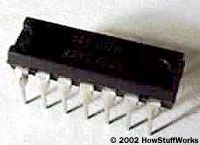
The 7400-series chips are housed in DIPs (dual inline packages). As pictured on the right, a DIP is a small plastic package with 14, 16, 20 or 24 little metal leads protruding from it to provide connections to the gates inside. The easiest way to construct something from these gates is to place the chips on a solderless breadboard. The breadboard lets you wire things together simply by plugging pieces of wire into connection holes on the board.
All electronic gates need a source of electrical power. TTL gates use 5 volts for operation. The chips are fairly particular about this voltage, so we will want to use a clean, regulated 5-volt power supply whenever working with TTL chips. Certain other chip families, such as the 4000 series of CMOS chips, are far less particular about the voltages they use. CMOS chips have the additional advantage that they use much less power. However, they are very sensitive to static electricity, and that makes them less reliable unless you have a static-free environment to work in. Therefore, we will stick with TTL here.
Advertisement
Assembling Your Equipment
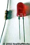
A resistor and an LED
In order to play with TTL gates, you must have several pieces of equipment. Here's a list of what you will need to purchase:
Some wire (20 to 28 gauge) to hook things together
These parts together might cost between $40 and $60 or so, depending on where you get them.
Advertisement
Let's walk through a few details on these parts to make you more familiar with them:
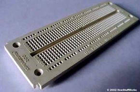
As described on the previous page, a breadboard is a device that makes it easy to wire up your circuits.
A volt-ohm meter lets you measure voltage and current easily. We will use it to make sure that our power supply is producing the right voltage.
The logic probe is optional. It makes it easy to test the state (1 or 0) of a wire, but you can do the same thing with an LED.
Of the parts described above, all are easy except the 5-volt power supply. No one seems to sell a simple, cheap 5-volt regulated power supply. You therefore have two choices. You can either buy a surplus power supply from Jameco (for something like a video game) and use the 5-volt supply from it, or you can use a little power-cube transformer and then build the regulator yourself. We will talk through both options below.
An LED (light emitting diode) is a mini light bulb. You use LEDs to see the output of a gate.
We will use the resistors to protect the LEDs. If you fail to use the resistors, the LEDs will burn out immediately.
This equipment is not the sort of stuff you are going to find at the corner store. However, it is not hard to obtain these parts. You have a few choices when trying to purchase the components listed above:
A local electronics parts store - Most major cities have electronics parts stores, and many cities are blessed with good surplus electronics stores. If you can find a good surplus store in your area that caters to people building their own stuff, then you have found a goldmine.
A mail-order house like Jameco - Jameco has been in business for decades, has a good inventory and good prices. (Be sure to download their PDF catalog or get a paper catalog from them -- it makes it much easier to traverse the Web site.)
Notes
*Jameco also has "assorted LEDs" (or grab bags) that are much cheaper on a per-LED basis. Look around and see what's available. This is one place where a surplus electronics shop will have much better prices.
If you are shopping at Jameco, you may want to get two or three of each chip just in case -- they only cost about 30 cents each. You might also want to purchase an extra 7805 or two.
You will also need a pair of wire cutters and wire strippers. In a pinch, you can use scissors and your fingernails, but having the proper tool makes it easier. You can get wire cutters and wire strippers at Jameco, Wal-mart, Radio Shack, and tons of other places. I also find that a small pair of needle nose pliers is helpful at times.
Advertisement
The Power Supply
You will definitely need a regulated 5-volt power supply to work with TTL chips. As mentioned previously, neither Radio Shack nor Jameco seem to offer a standard, inexpensive 5-volt regulated power supply. One option you have is to buy from Jameco something like part number 116089. This is a 5-volt power supply from an old Atari video game. If you look in the Jameco catalog, you will find that they have about 20 different surplus power supplies like this, producing all sorts of voltages and amperages. You need 5 volts at at least 0.3 amps (300 milliamps) -- you need no more than 2 amps, so do not purchase more power supply than you need. What you can do is buy the power supply, then cut off the connector and get access to the 5-volt and ground wires. That will work fine, and is probably the easiest path. You can use your volt meter (see below) to make sure the power supply produces the voltage you need.
Your alternative is to build a 5-volt supply from a little power-cube transformer. What you need is a transformer that produces 7 to 12 DC volts at 100 milliamps or more. Note that:
Advertisement
The transformer MUST produce DC voltage.
It MUST produce 7 to 12 volts.
It MUST produce 100 milliamps (0.1 amps) or more.
You may have an old one lying around that you can use -- read the imprint on the cover and make sure it meets all three requirements. If not, you can purchase a transformer from Radio Shack or Jameco.
Radio Shack sells a 9-volt 300-milliamp transformer (part number 273-1455). Jameco has a 7.5-volt 300-milliamp model (part number 149964). Clip the connector off the transformer and separate the two wires. Strip about a centimeter of insulation off both wires. Now plug the transformer in (once it is plugged in, NEVER let the two wires from the transformer touch one another or you are likely to burn out the transformer and ruin it). Use your volt meter (see below) to measure the voltage. You want to make sure that the transformer is producing approximately the stated voltage (it may be high by as much as a factor of two -- that is okay). Your transformer is acting like a battery for you, so you also want to determine which wire is the negative and which is the positive. Hook the black and red leads of the volt meter up to the transformer's wires randomly and see if the voltage measured is positive or negative. If it is negative, reverse the leads. Now you know that the wire to which the black lead is attached is the negative (ground) wire, while the other is the positive wire.
Using a Volt-Ohm Meter
A volt-ohm meter (multimeter) measures voltage, current and resistance. It has two "leads" (wires), one black and one red. What we want to do with the meter right now is learn how to measure voltage. To do this, find a AA, C or D battery to play with (not a dead one). We will use it as a voltage source.
Every meter is different, but in general, here are the steps to get ready to measure a battery's voltage:
Take your black test lead and insert it in the hole marked (depends on the meter) "Common," "Com," "Ground," "Gnd" or "-" (minus).
Take your red test lead and insert it in the hole marked (depends on the meter) "Volts," "V," "Pos" or "+" (plus). Some meters have multiple holes for the red lead -- make sure you use the one for volts.
Turn the dial to the "DC Volts" section. There will usually be multiple voltage ranges available in this section -- on my meter, the ranges are 2.5 volts, 50 volts, 250 volts and 1,000 volts (fancy auto-ranging meters may set the range for you automatically). Your meter will have similar ranges. The battery will have a voltage of 1.25 volts, so find the closest voltage greater than 1.25 volts. In my case, that is 2.5 volts.
Now, hold the black lead to the negative terminal of the battery and the red lead to the positive terminal. You should be able to read something close to 1.25 volts off the meter. It is important that you hook the black lead up to negative and the red lead up to positive and stay in the habit of doing that. Now you can use the meter to test your power supply, as well. Change the voltage range if necessary and then connect the black lead to ground and the red lead to what you presume to be the positive 5-volt wire. The meter should read 5 volts.
Advertisement
Building the Regulator
To build the regulator, you need three parts:
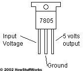
A 7805 5-volt voltage regulator in a TO-220 case (Radio Shack part number 276-1770)
Two electrolytic capacitors, anywhere between 100 and 1,000 microfarads (typical Radio Shack part number 272-958)
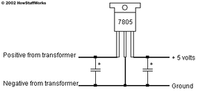
The 7805 takes in a voltage between 7 and 30 volts and regulates it down to exactly 5 volts. The first capacitor takes out any ripple coming from the transformer so that the 7805 is receiving a smooth input voltage, and the second capacitor acts as a load balancer to ensure consistent output from the 7805.
Advertisement
The three leads are, from left to right, input voltage (7 to 30 volts), ground and output voltage (5 volts).
The 7805 has three leads. If you look at the 7805 from the front (the side with printing on it), the three leads are, from left to right, input voltage (7 to 30 volts), ground, and output voltage (5 volts).
To connect the regulator to the transformer, you can use this configuration.
The two capacitors are represented by parallel lines. The "+" sign indicates that electrolytic capacitors are polarized: There is a positive and a negative terminal on an electrolytic capacitor (one of which will be marked). You need to make sure you get the polarity right when you install the capacitor.
You can build this regulator on your breadboard. To do this, you need to understand how a breadboard is internally wired.
On the outer edges of the breadboard are two lines of terminals running the length of the board. All of these terminals are internally connected. Typically, you run +5 volts down one of them and ground down the other. Down the center of the board is a channel. On either side of the channel are sets of five interconnected terminals. You can use your volt-ohm meter to see the interconnections. Set the meter's dial to its ohm setting, and then stick wires at different points in the breadboard (the test leads for the meter are likely too thick to fit in the breadboard's holes).
In the ohm setting, the meter measures resistance. Resistance will be zero if there is a connection between two points (touch the leads together to see this), and infinite if there is no connection (hold the leads apart to see this). You will find that points on the board really are interconnected as shown in the diagram. Another way to see the connections is to pull back the sticker on the back of the breadboard a bit and see the metal connectors.
Now connect the parts for your regulator:
Connect the ground wire of the transformer to one of the long outer strips on the breadboard.
Plug the 7805 into three of the five-hole rows.
Connect ground from the terminal strip to the middle lead of the 7805 with a wire -- simply cut a short piece of wire, strip off both ends and plug them in.
Connect the positive wire from the transformer to the left lead (input) of the 7805.
Connect a capacitor from the left lead of the 7805 to ground, paying attention to the polarity.
Connect the 5-volt lead of 7805 to the other long outer terminal strip on the breadboard.
Connect the second capacitor between the 5-volt and ground strips.
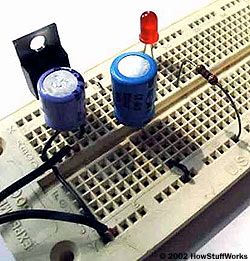
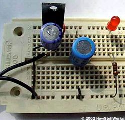
You have created your regulator. It might look like this when you are done (two views):
In both of the figures, the lines from the transformer come in from the left. You can see the ground line of the transformer connected directly into the ground strip running the length of the board at the bottom. The top strip supplies +5 volts and is connected directly to the +5 pin of the 7805. The left capacitor filters the transformer voltage, while the right capacitor filters the +5 volts produced by the 7805. The LED connects between the +5 and ground strips, through the resistor, and lets you know when the power supply is "on."
Plug in the transformer and measure the input and output voltage of the 7805. You should see exactly 5 volts coming out of the 7805, and whatever voltage your transformer delivers going in. If you do not, then immediately disconnect the transformer and do the following:
Pull out the capacitors. Plug the transformer back in for a moment and see if that changed anything.
Make sure the ground wire and positive wire from the transformer are not reversed (if they are, it is likely the 7805 is very hot, and possibly fried).
Make sure the transformer is producing any voltage at all by disconnecting it and checking it with your volt meter. See the previous page to learn how to do this.
Once you see 5 volts coming out of the regulator, you can test it further and see that it is on by connecting an LED to it. You need to connect an LED and a resistor in series -- something that is easy to do on your breadboard. You must use the resistor or the LED will burn out immediately. A good value for the resistor is 330 ohms, although anything between 200 and 500 ohms will work fine. LEDs, being diodes, have a polarity, so if your LED does not light, try reversing the leads and see if that helps.
It might seem like we've had to go to a tremendous amount of trouble just to get the power supply wired up and working. But you've learned a couple of things in the process. Now we can experiment with Boolean gates!
Advertisement
Playing with Boolean Gates
If you used the table on the previous page to order your parts, you should have six different chips containing six different types of gates:
7400 - NAND (four gates per chip)
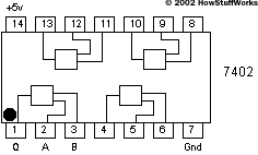
7402 - NOR (four gates per chip)
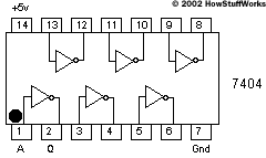
7404 - NOT (six gates per chip)
7408 - AND (four gates per chip)
7432 - OR (four gates per chip)
7486 - XOR (four gates per chip)
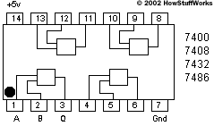
In this figure, the chip is receiving +5 volts on pin 14 (red wire) and ground on pin 7 (black wire). The resistor leaves pin 3 and connects to the LED, which is also connected to ground. Connect wires from +5 and ground to the gate's A and B inputs to exercise the gate.
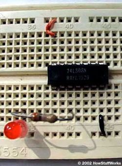
Let's start with a 7408 AND chip. If you look at the chip, there will normally be a dot at pin 1, or an indentation at the pin 1 end of the chip, or some other marking to indicate pin 1. Push the chip into the breadboard so it straddles the center channel. You can see from the diagrams that on all chips, pin 7 must connect to ground and pin 14 must connect to +5 volts. So connect those two pins appropriately. (If you connect them backward you will burn the chip out, so don't connect them backward. If you happen to burn a chip out accidentally, throw it away so you do not confuse it with your good parts.) Now connect an LED and resistor between pin 3 of the chip and ground. The LED should light. If not, reverse the LED so it lights. Your IC should look like this:
Advertisement
Here is what is happening. In TTL, +5 represents a binary "1" and ground represents a binary "0." If an input pin to a gate is not connected to anything, it "floats high," meaning the gate makes an assumption that there is a 1 on the pin. So the AND gate should be seeing 1s on both the A and B inputs, meaning that the output at pin 3 is delivering 5 volts. So the LED lights. If you ground either pin 1 or 2 or both on the chip, the LED will extinguish. This is the standard behavior for an AND gate, as described in How Boolean Logic Works.
Try out the other gates by connecting them on your breadboard and see that they all behave according to the logic tables in the Boolean logic article. Then try wiring up something more complicated. For example, wire up the XOR gate, or the Q bit of the full adder, and see that they behave as expected.
Advertisement
Build It!
In theory, you now have the fundamental knowledge you need to build any digital device. You can take the basic gates discussed in this article and construct anything. However, it is often more convenient to use larger-scale devices so that you don't have to combine 50 chips to build something common like an ALU. It is also helpful to see examples of different ways to combine gates to create complicated systems.
If you would like to work on a bigger project, you can try building the digital clock described in How Digital Clocks Work. If you want to learn more about TTL devices, the following books will be helpful:
Advertisement
You will be AMAZED at what you can create with just a few ICs and some creativity. Have fun with it!
For more information on electronic gates and related topics, check out the links on the next page.
Advertisement
Frequently Answered Questions
What are the three types of gates?
The three types of gates are the AND gate, the OR gate, and the NOT gate.
What are 7 logic gates?
The seven logic gates are: AND, OR, NOT, NAND, NOR, XOR, and XNOR.