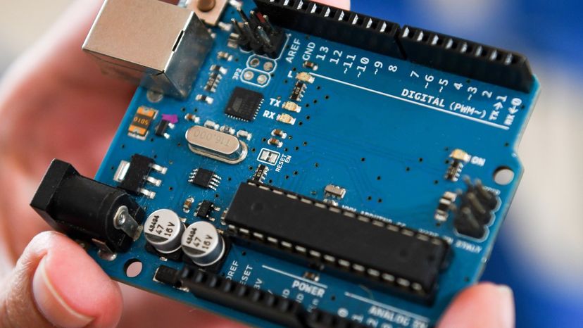
Microcontrollers are dedicated computers in electronics. Ernesto r. Ageitos / Getty Images
Microcontrollers are hidden inside a surprising number of products these days. If your microwave oven has an LED or LCD screen and a keypad, it contains a microcontroller. All modern automobiles contain at least one microcontroller, and can have as many as six or seven: The engine is controlled by a microcontroller, as are the anti-lock brakes, the cruise control and so on. Any device that has a remote control almost certainly contains a microcontroller: TVs, VCRs and high-end stereo systems all fall into this category. Nice SLR and digital cameras, cell phones, camcorders, answering machines, laser printers, telephones (the ones with caller ID, 20-number memory, etc.), pagers, and feature-laden refrigerators, dishwashers, washers and dryers (the ones with displays and keypads)... You get the idea. Basically, any product or device that interacts with its user has a microcontroller buried inside.
In this article, we will look at microcontrollers so that you can understand what they are and how they work. Then we will go one step further and discuss how you can start working with microcontrollers yourself -- we will create a digital clock with a microcontroller! We will also build a digital thermometer. In the process, you will learn an awful lot about how microcontrollers are used in commercial products.
A microcontroller is a computer. All computers -- whether we are talking about a personal desktop computer or a large mainframe computer or a microcontroller -- have several things in common:
All computers have a CPU (central processing unit) that executes programs. If you are sitting at a desktop computer right now reading this article, the CPU in that machine is executing a program that implements the Web browser that is displaying this page.
The CPU loads the program from somewhere. On your desktop machine, the browser program is loaded from the hard disk.
The computer has some RAM (random-access memory) where it can store "variables."
And the computer has some input and output devices so it can talk to people. On your desktop machine, the keyboard and mouse are input devices and the monitor and printer are output devices. A hard disk is an I/O device -- it handles both input and output.
The desktop computer you are using is a "general purpose computer" that can run any of thousands of programs. Microcontrollers are "special purpose computers." Microcontrollers do one thing well. There are a number of other common characteristics that define microcontrollers. If a computer matches a majority of these characteristics, then you can call it a "microcontroller":
Advertisement
Microcontrollers are "embedded" inside some other device (often a consumer product) so that they can control the features or actions of the product. Another name for a microcontroller, therefore, is "embedded controller."
Microcontrollers are dedicated to one task and run one specific program. The program is stored in ROM (read-only memory) and generally does not change.
Microcontrollers are often low-power devices. A desktop computer is almost always plugged into a wall socket and might consume 50 watts of electricity. A battery-operated microcontroller might consume 50 milliwatts.
A microcontroller has a dedicated input device and often (but not always) has a small LED or LCD display for output. A microcontroller also takes input from the device it is controlling and controls the device by sending signals to different components in the device. For example, the microcontroller inside a TV takes input from the remote control and displays output on the TV screen. The controller controls the channel selector, the speaker system and certain adjustments on the picture tube electronics such as tint and brightness. The engine controller in a car takes input from sensors such as the oxygen and knock sensors and controls things like fuel mix and spark plug timing. A microwave oven controller takes input from a keypad, displays output on an LCD display and controls a relay that turns the microwave generator on and off.
A microcontroller is often small and low cost. The components are chosen to minimize size and to be as inexpensive as possible.
A microcontroller is often, but not always, ruggedized in some way. The microcontroller controlling a car's engine, for example, has to work in temperature extremes that a normal computer generally cannot handle. A car's microcontroller in Alaska has to work fine in -30 degree F (-34 C) weather, while the same microcontroller in Nevada might be operating at 120 degrees F (49 C). When you add the heat naturally generated by the engine, the temperature can go as high as 150 or 180 degrees F (65-80 C) in the engine compartment. On the other hand, a microcontroller embedded inside a VCR hasn't been ruggedized at all.
The actual processor used to implement a microcontroller can vary widely. For example, the cell phone shown on Inside a Digital Cell Phone contains a Z-80 processor. The Z-80 is an 8-bit microprocessor developed in the 1970s and originally used in home computers of the time. The Garmin GPS shown in How GPS Receivers Work contains a low-power version of the Intel 80386, I am told. The 80386 was originally used in desktop computers.
In many products, such as microwave ovens, the demand on the CPU is fairly low and price is an important consideration. In these cases, manufacturers turn to dedicated microcontroller chips -- chips that were originally designed to be low-cost, small, low-power, embedded CPUs. The Motorola 6811 and Intel 8051 are both good examples of such chips. There is also a line of popular controllers called "PIC microcontrollers" created by a company called Microchip. By today's standards, these CPUs are incredibly minimalistic; but they are extremely inexpensive when purchased in large quantities and can often meet the needs of a device's designer with just one chip.
A typical low-end microcontroller chip might have 1,000 bytes of ROM and 20 bytes of RAM on the chip, along with eight I/0 pins. In large quantities, the cost of these chips can sometimes be just pennies. You certainly are never going to run Microsoft Word on such a chip -- Microsoft Word requires perhaps 30 megabytes of RAM and a processor that can run millions of instructions per second. But then, you don't need Microsoft Word to control a microwave oven, either. With a microcontroller, you have one specific task you are trying to accomplish, and low-cost, low-power performance is what is important.
Advertisement
Using Microcontrollers
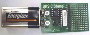
A BASIC Stamp is a PIC microcontroller that has been customized to understand the BASIC programming language.
In How Electronic Gates Work, you learned about 7400-series TTL devices, as well as where to buy them and how to assemble them. What you found is that it can often take many gates to implement simple devices. For example, in the digital clock article, the clock we designed might contain 15 or 20 chips. One of the big advantages of a microcontroller is that software -- a small program you write and execute on the controller -- can take the place of many gates. In this article, therefore, we will use a microcontroller to create a digital clock. This is going to be a rather expensive digital clock (almost $200!), but in the process you will accumulate everything you need to play with microcontrollers for years to come. Even if you don't actually create this digital clock, you will learn a great deal by reading about it.
The microcontroller we will use here is a special-purpose device designed to make life as simple as possible. The device is called a "BASIC Stamp" and is created by a company called Parallax. A BASIC Stamp is a PIC microcontroller that has been customized to understand the BASIC programming language. The use of the BASIC language makes it extremely easy to create software for the controller. The microcontroller chip can be purchased on a small carrier board that accepts a 9-volt battery, and you can program it by plugging it into one of the ports on your desktop computer. It is unlikely that any manufacturer would use a BASIC Stamp in an actual production device -- Stamps are expensive and slow (relatively speaking). However, it is quite common to use Stamps for prototyping or for one-off demo products because they are so incredibly easy to set up and use.
Advertisement
They are called "Stamps," by the way, because they are about as big as a postage stamp.
The specific BASIC Stamp we will be using in this article is called the "BASIC Stamp Revision D".
The BASIC Stamp Revision D is a BS-1 mounted on carrier board with a 9-volt battery holder, a power regulator, a connection for a programming cable, header pins for the I/O lines and a small prototyping area. You could buy a BS-1 chip and wire the other components in on a breadboard. The Revision D simply makes life easier.
You can see from the previous table that you aren't going to be doing anything exotic with a BASIC stamp. The 75-line limit (the 256 bytes of EEPROM can hold a BASIC program about 75 lines long) for the BS-1 is fairly constraining. However, you can create some pretty neat stuff, and the fact that the Stamp is so small and battery operated means that it can go almost anywhere.
Advertisement
Programming the BASIC Stamp
You program a BASIC Stamp using the BASIC programming language. If you already know BASIC, then you will find that the BASIC used in a Stamp is straightforward but a little stripped-down. If you don't know BASIC, but you do know another language like C, Pascal or Java, then picking up BASIC will be trivial. If you have never programmed before, you probably want to go learn programming on a desktop machine first. Here is a quick rundown on the instructions available in Stamp BASIC. (For complete documentation, go to Parallax: BASIC Stamp Documentation.)
Standard BASIC instructions:
for...next - normal looping statement
gosub - go to a subroutine
goto - goto a label in the program (e.g. - "label:")
if...then - normal if/then decision
let - assignment (optional)
return - return from a subroutine
end - end the program and sleep
Instructions having to do with I/O pins:
button - read a button on an input pin, with debounce and auto-repeat
high - set an I/O pin high
input - set the direction of an I/O pin to input
low - set an I/O pin low
output - set the direction of an I/O pin to output
pot - read a potentiometer on an I/O pin
pulsin - read the duration of a pulse coming in on an input pin
pulsout - send a pulse of a specific duration out on an output pin
pwm - perform pulse width modulation on an output pin
reverse - reverse the direction of an I/O pin
serin - read serial data on an input pin
serout - write serial data on an output pin
sound - send a sound of a specific frequency to an output pin
toggle - toggle the bit on an output pin
Instructions specific to the BASIC Stamp:
branch - read a branching table
debug - send a debugging string to the console on the desktop computer
eeprom - download a program to EEPROM
lookdown - return the index of a value in a list
lookup - array lookup using an index
nap - sleep for a short time
pause - delay for the specified time
random - pick a random number
read - read a value from EEPROM
sleep - power down for the specified time
write - write data to EEPROM
Operations:
+ - addition
- - subtraction
* - multiplication (low-word)
** - multiplication (high-word)
/ - division
// - mod
max - return maximum of 2 values
min - return minimum of 2 values
& - AND
| - OR
^ - XOR
&/ - NAND
|/ - NOR
^/ - XNOR
If statement logic:
=
Advertisement
<>
<
<=
>
>=
AND
OR
Variables
All variables in the BS-1 have pre-defined names (which you can substitute with names of your own). Remember that there are only 14 bytes of RAM available, so variables are precious. Here are the standard names:
w0, w1, w2...w6 - 16-bit word variables
b0, b1, b2...b13 - 8-bit byte variables
bit0, bit1, bit2...bit15 - 1-bit bit variables
Because there are only 14 bytes of memory, w0 and b0/b1 are the same locations in RAM, and w1 and b2/b3 are the same, and so on. Also, bit0 through bit15 reside in w0 (and therefore b0/b1 as well).
I/O pins
You can see that 14 of the instructions in the BS-1 have to do with the I/O pins. The reason for this emphasis is the fact that the I/O pins are the only way for the BASIC Stamp to talk to the world. There are eight pins on the BS-1 (numbered 0 to 7) and 16 pins on the BS-2 (numbered 0 to 15).
The pins are bi-directional, meaning that you can read input values on them or send output values to them. The easiest way to send a value to a pin is to use the HIGH or LOW functions. The statement high 3 sends a 1 (+5 volts) out on pin 3. LOW sends a 0 (Ground). Pin 3 was chosen arbitrarily here -- you can send bits out on any pin from 0 to 7.
There are a number of interesting I/O pin instructions. For example, POT reads the setting on a potentiometer (variable resistor) if you wire it up with a capacitor as the POT instruction expects. The PWM instruction sends out pulse-width modulated signals. Instructions like these can make it a lot easier to attach controls and motors to the Stamp. See the documentation for the language for details. Also, a book like Scott Edward's Programming and Customizing the BASIC Stamp Computer can be extremely helpful because of the example projects it contains.
Advertisement
Playing with a BASIC Stamp
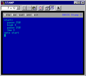
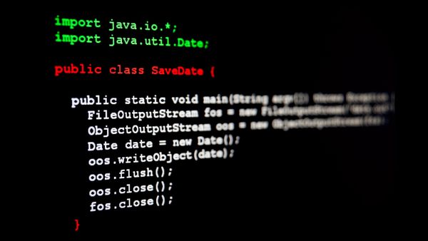
A screenshot of a typical BASIC program editor
If you would like to play with a BASIC Stamp, it's very easy to get started. What you need is a desktop computer and a BASIC Stamp starter kit. The starter kit includes the Stamp, a programming cable and an application that you run on your desktop computer to download BASIC programs into the Stamp.
You can get a starter kit either from Parallax (the manufacturer) or from a supplier like Jameco (who should be familiar to you from the electronic gates and digital clock articles). From Parallax, you can order the BASIC Stamp D Starter Kit (part number 27202), or from Jameco you can order part number 140089. You will receive the Stamp (pictured below), a programming cable, software and instructions. The kit is $79 from both suppliers. Occasionally, Parallax runs a special called "We've Bagged the Basics" that also includes Scott Edward's Programming and Customizing the BASIC Stamp Computer].
Advertisement
Hooking up the Stamp is easy. You connect it into the parallel port of your PC. Then you run a DOS application to edit your BASIC program and download it to the Stamp.
To run the program in this editor, you hit ALT-R. The editor application checks the BASIC program and then sends it down the wire to the EEPROM on the Stamp. The Stamp then executes the program. In this case, the program produces a square wave on I/O pin 3. If you hook up a logic probe or LED to pin 3 (see the electronic gates article for details), you will see the LED flash on and off twice per second (it changes state every 250 milliseconds because of the PAUSE commands). This program would run for several weeks off of a 9-volt battery. You could save power by shortening the time that the LED is on (perhaps it is on for 50 milliseconds and off for 450 milliseconds), and also by using the NAP instruction instead of PAUSE.
Advertisement
Creating a Really Expensive Digital Clock
Spending $79 to flash an LED may seem extravagant to you. What you would probably like to do is create something useful with your BASIC stamp. By spending about $100 more you can create a really nice digital clock! This may seem extremely extravagant, until you realize that the parts are reusable in a variety of other projects that you may want to build later.
Let's say that we would like to use the I/O pins on the BASIC Stamp to display numeric values. In the digital clock article, we saw how to interface to a 7-segment LED display using a 7447 chip. 7447s would work just as well with the BASIC Stamp. You could wire four of the I/O pins straight into a 7447 and easily display a number between 0 and 9. Since the BS-1 Stamp has eight I/O pins, it is easy to drive two 7447s directly like this.
Advertisement
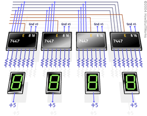
For a clock, we need a minimum of four digits. To drive four 7447s with eight I/O pins, we have to be slightly more creative. The following diagram shows you one approach:
In this diagram, the eight I/O lines from the Stamp enter from the left. This approach uses four lines that run to all four 7447s. Then the other four lines from the Stamp activate the 7447s in sequence ("E" on the chips means "Enable" -- on a 7447, that would be the blanking input on pin 5). To make this arrangement work, the BASIC program in the Stamp would output the first digit on the four data lines and activate the first 7447 by toggling its E pin with the first control line. Then it would send out the value for the second digit and activate the second 7447, sequencing through all four of the 7447s like this repeatedly. By wiring things slightly differently, you could actually do this with only one 7447. By using a 74154 demultiplexer chip and some drivers, you could drive up to 16 digits using this approach.
This is, in fact, a standard way to control LED displays. For example, if you have an old LED calculator, turn it on and shake it while watching the display. You will actually be able to see that only one digit is ever illuminated at once. The approach is called multiplexing the display.
While this approach works fine for clocks and calculators, it has two important problems:
LEDs consume a lot of power.
7-segment LEDs can only display numeric values.
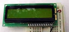
An alternative approach is to use an LCD screen. As it turns out, LCDs are widely available and can be easily hooked to a Stamp. For example, the two-line by 16-character alphanumeric display shown below is available from both Jameco (part number 150990) and Parallax (part number 27910). A typical display is shown here, mounted on a breadboard for easier interfacing:
This sort of LCD has several advantages:
The display can be driven by a single I/O pin. The display contains logic that lets a Stamp communicate with it serially, so only one I/O pin is needed. In addition, the SEROUT command in Stamp BASIC handles serial communication easily, so talking to the display is simple.
The LCD can display alphanumeric text: letters, numbers and even custom characters.
The LCD consumes very little power -- only 3 milliamps.
The only problem is that one of these displays costs $59. Obviously, you would not embed one of these in a toaster oven. If you were designing a toaster oven, however, you would likely prototype with one of these displays and then create custom chips and software to drive much cheaper LCDs in the final product.
To drive a display like this, you simply supply it with +5 volts and ground (the Stamp supplies both from the 9-volt battery) and then hook one of the I/O pins from the Stamp to the display's input line. The easiest way I have found to connect the Stamp's I/O pins to a device like an LCD is to use a wire-wrap tool (Jameco part number 34577) and 30-gauge wire wrap wire (Jameco part number 22541 is typical). That way, no soldering is involved and the connections are compact and reliable.
The following BASIC program will cause a BASIC Stamp to behave like a clock and output the time on the LCD (assuming the LCD is connected to I/O pin 0 on the Stamp):
pause 1000                 'wait for LCD display to boot
serout 0, n2400, (254, 1)  'clear the display
serout 0, n2400, ("time:") 'Paint "time:" on the display
                'preset before loading program
b0 = 0                     'seconds
b1 = 27                    'minutes
b2 = 6                     'hours

again:
b0 = b0 + 1                'increment seconds
if b0 < 60 then minutes
  b0 = 0                   'if seconds=60
  b1 = b1 + 1              ' then increment minutes
minutes:
if b1 < 60 then hours
  b1 = 0                   'if minutes=60
  b2 = b2 + 1              '  then increment hours
hours:
if b2 < 13 then show
  b2 = 1                   'if hours=13 reset to 1

show:
serout 0, n2400, (254, 135) 'position cursor on display,
                            'then display time
serout 0, n2400, (#b2, ":", #b1, ":", #b0, "    ")
pause 950                     'pause 950 milliseconds
goto again                    'repeat
In this program, the SEROUT commands send data to the LCD. The sequence (254, 1) clears the LCD (254 is the escape character and 1 is the command to clear the screen). The sequence (254, 135) positions the cursor. The other two SEROUT commands simply send text strings to the display.
This approach will create a reasonably accurate clock. By tweaking the PAUSE statement you can get the accuracy to within a few seconds a day. Obviously, in a real clock you would like to wire up a push-button or two to make setting it easier -- in this program, you preset the time before you download the program to the Stamp.
Pocket Watch B Module
While this approach is simple and works, it is not incredibly accurate. If you want better accuracy, one good approach would be to wire a real-time clock chip up to your Stamp. Then, every second or so, you can read the time from the chip and display it. A real-time clock chip uses a quartz crystal to give it excellent accuracy. Clock chips also usually contain date information and handle leap year correction automatically.
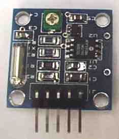
One easy way to interface a real-time clock to a stamp is to use a component called the Pocket Watch B.
The Pocket Watch B is available from both Jameco (part number 145630) and Parallax (part number 27962). This part is about as big as a quarter and contains the clock chip, crystal and a serial interface so that only one I/O pin is necessary to communicate with it. This component costs about $30 -- again, not something you want to embed in a toaster oven, but easy to play with when constructing prototypes.
Advertisement
Building a Digital Thermometer
Now that you understand a little bit about your Stamp and the LCD, we can add another component and create a digital thermometer. To create a thermometer, we will use a chip called the DS1620. This chip contains:
A temperature-sensing device
An analog-to-digital (A/D) converter for the temperature-sensing device
A shift register to read the data out of the A/D converter
A little EEPROM (electrically erasable programmable read-only memory) to remember settings
The DS1620 has two modes: In one mode, it acts as a stand-alone thermostat chip, and in the other mode you hook it up to a computer and use it as a thermometer. The EEPROM remembers the current mode as well as the set temperatures for the thermostat.
Advertisement
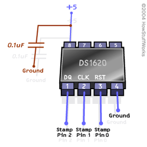
Hooking up the DS1620 to the Stamp is very easy. The DS1620 comes in an 8-pin chip. Supply +5 volts from the Stamp to pin 8 of the DS1620. Supply ground to pin 4 of the DS1620. You then use three I/O pins from the Stamp to drive three pins on the DS1620:
Pin 1 on the DS1620 is the data pin. You read and write data bits on this pin.
Pin 2 on the DS1620 is the clock pin. You clock data in and out of the shift register with this pin.
Pin 3 on the DS1620 is the reset/select pin. You set pin 3 high to select the chip and communicate with it.
For this example code, it is assumed that:
The data pin goes to I/O pin 2 on the Stamp.
The clock pin goes to I/O pin 1 on the Stamp.
The reset/select pin goes to I/O pin 0 on the Stamp.
The completed wiring looks like this:
You can get a DS1620 either from Jameco (part number 146456) or Parallax (part number 27917) in an "application kit" that includes the chip, the capacitor, some good documentation and sample code. Or you can buy the chip on its own from Jameco (part number 114382). I would suggest getting the application kit the first time you try using the DS1620 because the documentation is very useful.
You can assemble the DS1620 in the prototype area of the Stamp carrier board or on a separate breadboard. Once you have assembled it, hook your LCD display up to I/O pin 3 of the Stamp, and then load and run the following program:
symbol RST = 0 ' select/reset line on 1620
symbol CLK = 1 ' clock line for shift registers on 1620
symbol DQ = 2  ' data line on 1620
symbol DQ_PIN = pin2 ' pin representation for DQ
symbol LCD = 3 ' data line for LCD

begin:
low RST     ' deselect the 1620 unless talking to it
high CLK    ' clock pin on 1620 should default high
pause 1000  ' wait for the thermometer and LCD to boot

setup:
high RST        ' select the 1620
b0 = $0C        ' $0c is the 1620 command byte
                '   saying "Write Config"
gosub shift_out ' send it to the 1620
b0 = %10        ' %10 is the 1620 command byte
                '   to set thermometer mode
gosub shift_out ' send it to the 1620
low RST         ' deselect the 1620
pause 50        ' delay 50ms for EEPROM

start_convert:
b0 = $EE        ' $EE is the 1620 command byte
                '   to start conversions
high RST        ' select the 1620
gosub shift_out ' send it to the 1620
low RST         ' deselect the 1620

' This is the main loop
' - reads and displays temperature every second
main_loop:
  high RST        ' select the 1620
  b0 = $AA        ' $AA is the 1620 command byte
                  '   for reading temperature
  gosub shift_out ' send it to the 1620
  gosub shift_in  ' read the temperature
                  '   from the 1620
  low RST         ' deselect the DS1620.
  gosub display   ' display the temp in degrees C
  pause 1000      ' wait a second
goto main_loop

' The shift_out subroutine sends whatever is in
' the b0 byte to the 1620
shift_out:
output DQ           ' set the DQ pin to
                    '   output mode
for b2 = 1 to 8
  low CLK           ' prepare to clock the bit
                    '   into 1620
  DQ_PIN = bit0     ' Send the data bit
  high CLK          ' latch data bit into 1620
  b0 = b0/2         ' shift all bits right
                    '   toward bit 0
next
return

' The shift_in subroutine gets a 9-bit
' temperature from the 1620
shift_in:
input DQ            ' set the DQ pin to
                    '   input mode
w0 = 0              ' clear w0
for b5 = 1 to 9
  w0 = w0/2         ' shift input right.
  low CLK           ' ask 1620 for next bit
  bit8 = DQ_PIN     ' read the bit
  high CLK          ' toggle clock pin
next
return

' Displays the temperature in degrees C
display:
if bit8 = 0 then pos      ' if bit8=1
                          '   then temp is negative
  b0 = b0 &/ b0           ' invert b0 by NANDing it
                          '   with itself
  b0 = b0 + 1
pos:
serout LCD, n2400, (254, 1)    ' clear the LCD
serout LCD, n2400, ("Temp = ") ' display "Temp="
                               '   on the display
bit9 = bit0                    ' save the half degree
b0 = b0 / 2                    ' convert to degrees
if bit8 = 1 then neg           ' see if temp is negative
  serout LCD, n2400, (#b0)     ' display positive temp
  goto half
neg:
  serout LCD, n2400, ("-", #b0)' display negative temp
half:
  if bit9 = 0 then even
    serout LCD, n2400, (".5 C") ' display the half degree
    goto done
even:
    serout LCD, n2400, (".0 C") ' display the half degree
done:
return
If you run this program, you will find that it displays the centigrade temperature with an accuracy of one-half degree.
The DS1620 measures temperatures in centigrade half-degrees. It returns the temperature in a 9-bit 2s-complement number with a range of -110 to 250 F (-55 to 125 C). You divide the number you receive by 2 to get the actual temperature. 2s-complement binary numbers are a convenient way to represent negative values. The following list shows the values for a 4-bit 2s-complement number:
You can see that instead of the 4 bits representing values from 0 to 15, the 4 bits in a 2s-complement number represent the values -8 to 7. You can look at the left-most bit to determine if the number is negative or positive. If the number is negative, you can invert the bits and add 1 to get the positive representation of the number.
Here's what goes on with the digital thermometer program shown here:
It uses the symbol keyword to set up several constants that make the program slightly easier to read (and also make it easy for you to move the chip to different I/O pins on the Stamp).
It sets the CLK and RST pins on the DS1620 to their expected values.
It writes a command byte to the EEPROM on the DS1620 to tell the chip to operate in "thermometer mode." Because the mode is stored in EEPROM, you only have to do it once, so you could technically take this section of the code out of the program after you run the program once (to save program space).
The program sends the command $EE ("$" means "hexadecimal number" -- $EE is 238 in decimal) to tell the thermometer to start up its conversion process.
The program then enters a loop. Every second, it sends a command to the DS1620 telling the DS1620 to return the current temperature, and then it reads the 9-bit value that the DS1620 returns into the w0 variable. The Stamp sends and receives data 1 bit at a time by toggling the CLK line on the DS1620. Remember that the w0 (16-bit) variable overlays the b0/b1 (8-bit) variables, which overlay the bit0/bit1/.../bit15 (1-bit) variables, so when you insert a bit from the DS1620 into bit 8 and divide w0 by 2, what you are doing is shifting each bit to the right to store the 9-bit temperature from the DS1620 into w0. Once the temperature has been saved in w0, the display subroutine determines whether the number is positive or negative and displays it appropriately on the LCD as a centigrade temperature. The conversion from degrees C to degrees F is:
dF = dC * 9/5 + 32
At this point, we have succeeded in creating an extremely expensive thermometer. What might you do with it? Here's one idea. Let's say you work for a drug company and you are shipping expensive drugs across the country that MUST remain at a certain temperature the entire way or the drugs will spoil. What you can do with a Stamp is create a data logging thermometer. Both Jameco (part number 143811) and Parallax (part number 27960) sell a device called the "RAM Pack module." It contains a low-power 8-kilobyte (or optionally 32-kilobyte) RAM chip with a serial interface. You could add this component (or something similar) to your Stamp and write code that saves temperature readings to the RAM every minute. You could then slip your Stamp into the drug shipment, and at the other end of the trip retrieve the Stamp. The RAM module would contain the temperature history of the entire trip and you would know whether or not the drugs ever thawed out.
There are all kinds of neat, useful devices like this that you can build with a Stamp now that you know how microcontrollers work!
For more information on microcontrollers and related topics, check out the links on the next page.